


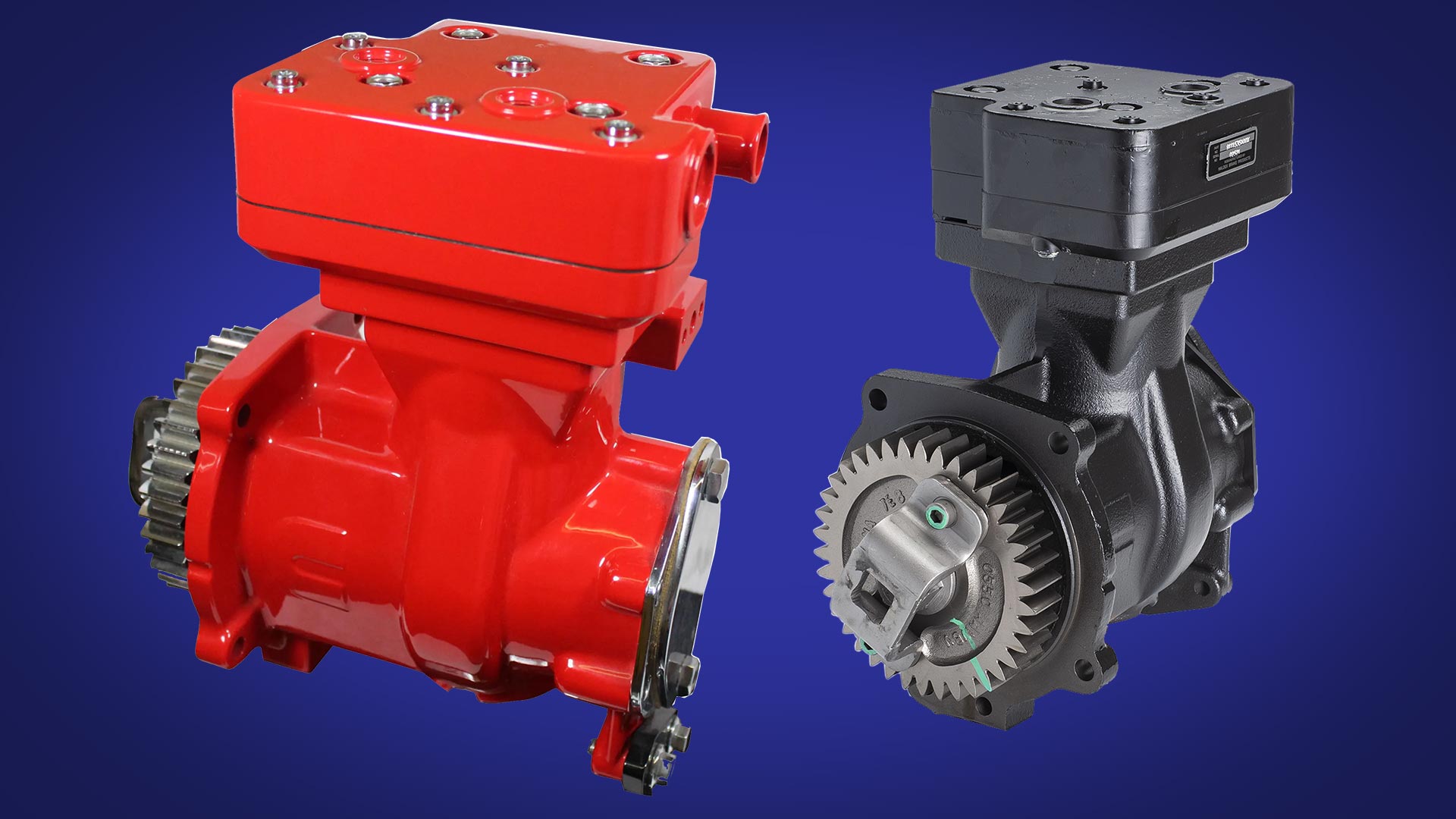
The primary function of a truck air compressor is to supply compressed air for the truck air suspension and braking system.
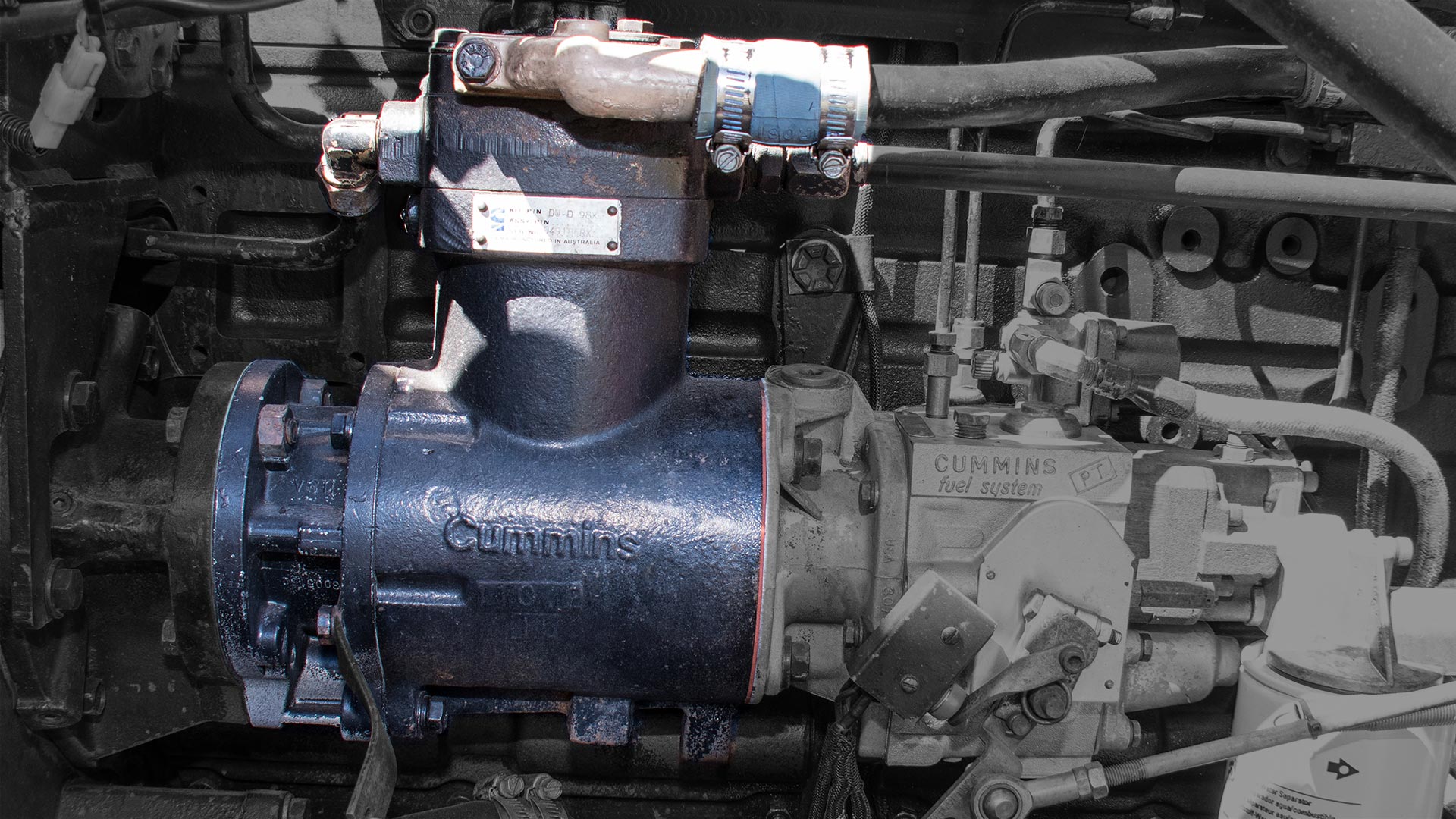 Typically, this type of compressor is driven by the truck’s engine. The air compressor builds the air pressure for the air suspension, auxiliary components and brake system. In most cases, the air compressor is lubricated via the engine oil supply and cooled with the engine’s coolant.
Depending on the compressor model, it will draw filtered air, either naturally aspirated (at atmospheric pressure) directly from the truck air-cleaner or already at increased pressure from the engine’s turbocharger. Then, it compresses the air until it reaches the required system pressure.
 Brake Function
The brake system requires a constant compressed air supply within a predetermined maximum and minimum pressure to function correctly.
All compressors have a governor which monitors the air pressure in the supply reservoir and monitors when the compressor needs to pump air into the air system – this is called the “air build cycle” where the compressor is running loaded. Once the system has sufficient air, the compressor can turn over without building pressure, called “running unloaded”.
The governor also monitors when the air pressure in the system becomes greater than that of the preset “cut-out”. When the air pressure exceeds the preset pressure, the governor activates the unloader mechanism of the compressor, stops the compressor from building air and causes the air dryer to purge. As the service reservoir air pressure drops to the “cut-in” setting (preset minimum) of the governor, the governor then returns the compressor to building air and cycles the air dryer back to air drying mode.
During this process, the atmospheric air gets compressed. As a result, all the water vapour originally in the air now travels into the air system. Furthermore, a small amount of the compressor lubricating oil gets transferred into the system as a form of vapour.
 Duty Cycle
The compressor duty cycle is the ratio of time it spends building air relative to the total engine running time. Truck air compressors build up air pressure or run “loaded” up to 25 per cent of the time. Suppose a compressor runs higher duty cycles, which then causes higher compressor head temperatures that may adversely affect air brake system performance. In addition, continual high duty cycles mean that the air system will require additional maintenance due to more oil vapour droplets passing into the air brake system.
Factors that can cause unnecessary air compressor higher duty cycles are;
- Undersized compressor
- Additional air accessories
- Frequent brake applications
- Air system leaks (from fittings, connections, chambers or valves)
- Excessive air suspension oscillation.
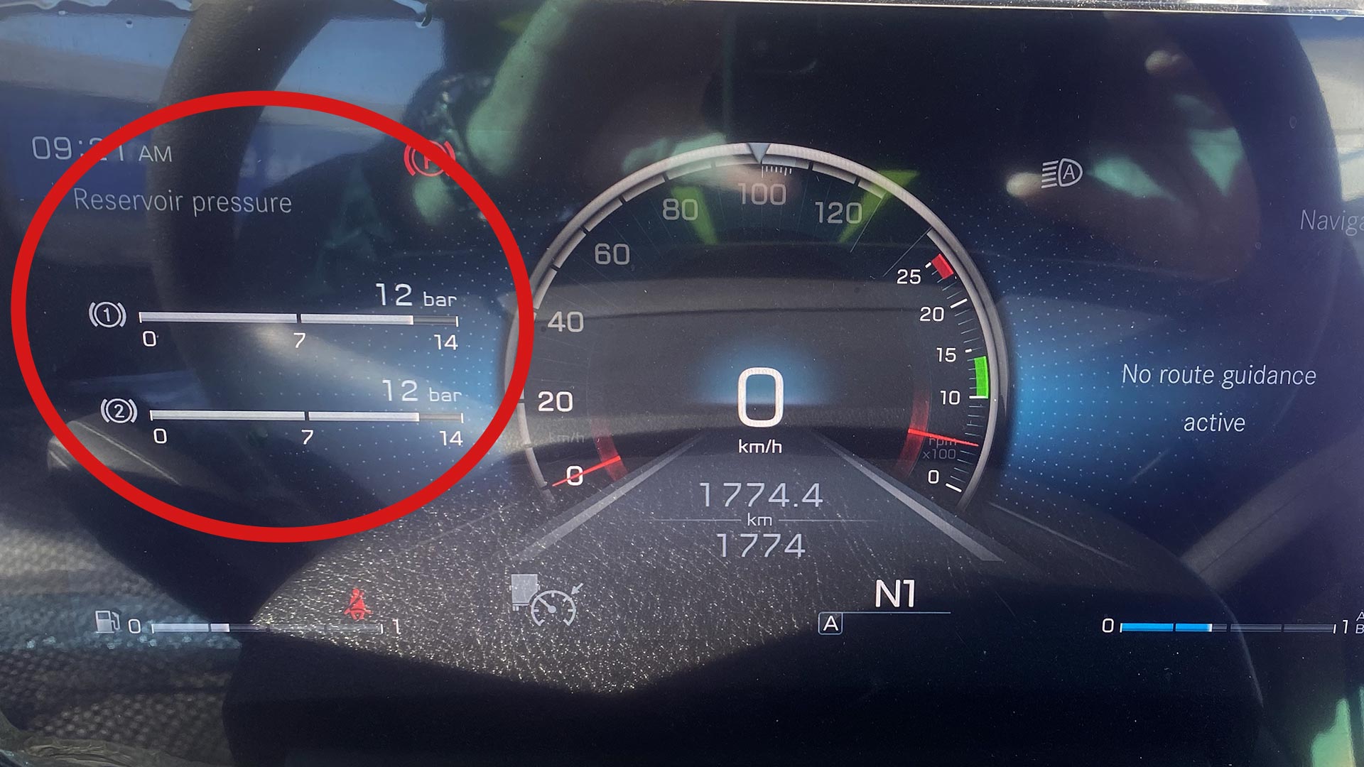
Mercedes-Benz Actros air gauges
One of the most common air compressors found on modern trucks today is a Wabco SS318 Series Air Compressor or similar. It is a single-cylinder compressor with a rated displacement output of 18.7 CFM at 1250 RPM. To test if the air compressor duty cycle functions normally while charging the air system. First, disconnect the air supply to any trailers so that the compressor is only charging the prime mover air system. Next, watch the air gauges, reduce the air pressure to 85 PSI (586kpa) by depressing the foot brake pedal and verify that the air compressor builds air up to 100 PSI (690kpa) in 40seconds or less with the engine at full governed rpm. If the air compressor takes longer than 40 seconds to build up the air during this test, it indicates there is something wrong with the compressor, and it will require servicing by an authorised dealer.
Air System Operation
The discharge line allows the air, water, and oil vapour mixture to cool between the compressor and the air dryer. The inlet temperatures of the air dryer play a vital role in air system cleanliness and air dryer performance. For instance, when the compressed air temperature enters the air dryer within the normal range, the air dryer removes most of the charging system oil. On the other hand, if the compressed air temperature is above the normal range, oil in the form of oil vapour can pass through the air dryer and into the air system. For this reason, many truck manufacturers use larger diameter discharge lines or longer discharge line lengths to reduce the temperature of compressed air before it enters the air dryer.
The route of the discharge line from the engine to the air dryer also plays a critical part in air system efficiency. The discharge line must maintain a constant slope down from the compressor to the air dryer inlet fitting to avoid any low points where ice may form and block airflow. While not such a problem for truck operators at the northern end of Australia, where the ambient temperature rarely falls below 20 degrees Celsius. In the southern parts of the continent and alpine areas, the discharge line route mustn’t contain any bends that will enhance the formation of ice in the line.
 Air Supply
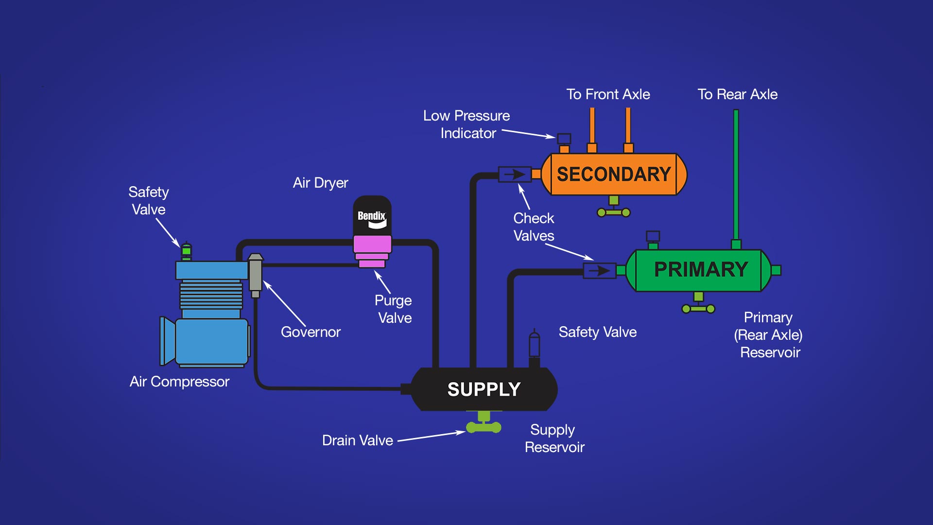
Compressed air travels from the air dryer into the air reservoirs or air tanks, as they are more commonly called. Air is typically delivered to the primary brake system reservoir first and then to the secondary brake system reservoir. Once both the prime mover’s brake circuits are fully charged, it is then possible to supply air to any attached trailer reservoirs. For each system, the air pressurises the reservoir and the air hoses all the way to the next control valve, where the air pressure remains, ready to use.
Trucks use compressed air for tasks other than the air suspension and brake system. For instance, automated transmissions require at least 758kpa (110 PSI) to operate their shifter mechanisms. Horton fan clutches require air pressure to engage. Road train operators use compressed air to transfer fuel from trailer belly tanks to the prime-mover fuel tanks. And the list goes on.
 Normal Braking
When the driver presses down on the foot brake, the plunger within the foot brake treadle valve moves, opening channels within the treadle valve that allow the air pressure waiting there to pass through to the primary and secondary brake systems. Now the air pressure quickly increases in the brake chambers, thereby applying force to the brake pushrod, transferring this force to the air disc brake or via a slack adjuster to a foundation drum brake. When the brake pedal is released, the air in the brake chambers quickly expels, allowing the brake pads or shoes to return to their normal travelling position.
Vehicle Parking
Vehicles are parked using powerful springs incorporated into the spring brake assembly. To engage the brakes and hold the truck in position. When the driver prepares to move away and releases the parking brake, the spring force gets countered with the introduction of air pressure, and the brake pad returns to the travelling position. An anti-compounding valve in the system design helps prevent the application of both the spring and service brakes together.
 Air Pressure Gauges
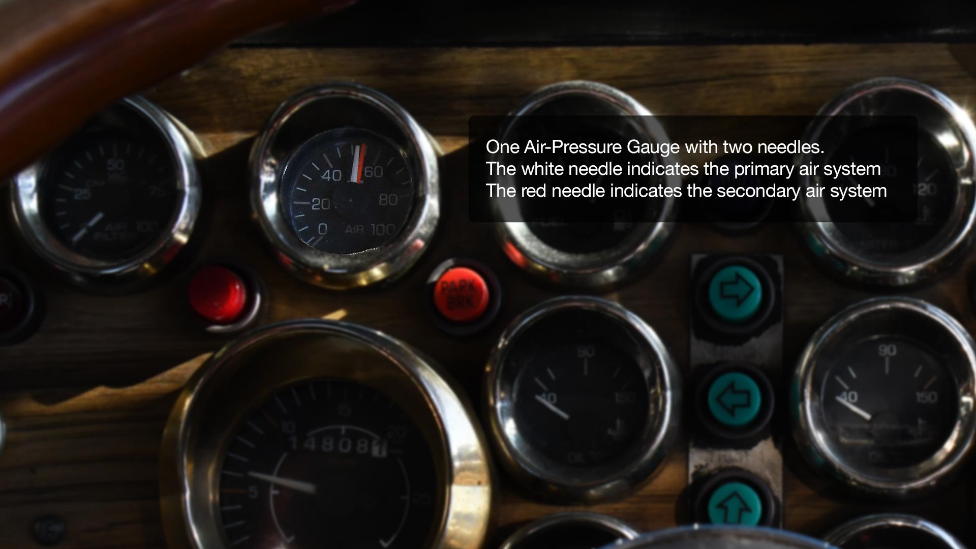
In the early seventies, government regulations mandated that vehicles equipped with air brakes incorporate a dual circuit air system. The benefit of the dual circuit air system meant that in the event of a failure in the primary circuit, the vehicle can still stop using the second separate air circuit only.
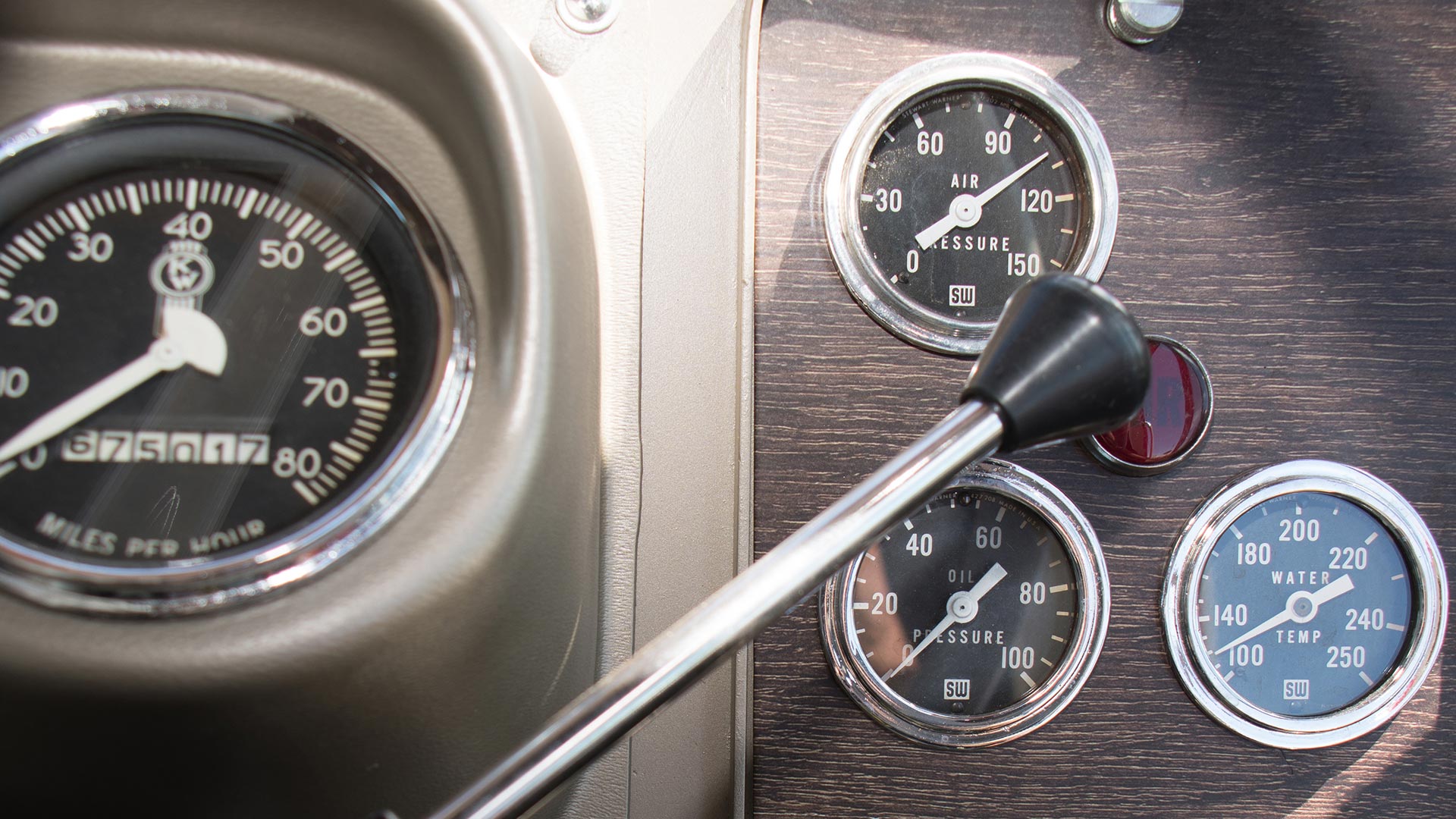
Consequently, this is why there are two air pressure gauges in trucks today—one gauge for the primary circuit and another for the secondary brake circuit. The gauges for both air systems show how much air gets consumed during braking and when the compressor activates to build up pressure. If you notice frequent activation of the compressor cycling ‘on’ and ‘off’ or an excessive air loss in either system during braking, pull over at a safe place and perform the 2-minute/5-PSI (35kpa) leakage test.
Air System Leakage Test
Use this simple method to test air system integrity while on the road or during your prestart procedure. First and most importantly, park on level ground and chock the wheels so the truck will not roll. Let the truck build up full air pressure. Release the park brakes. Now turn off the engine, but leave the key in the ‘on’ position so you can read the air pressure gauges. Then press the foot brake pedal down as far as it goes to make a full brake application for at least 2-minutes. At the same time, watch the air pressure gauges. Leakage, if present, should be less than 5-PSI (35kpa) for the entire two minutes. To test that the low air pressure audible warning alert is functioning correctly. Continue to pump the brake pedal to release air from the system. When the air pressure drops below 60-PSI (414kpa), both an audible and visual warning should sound and be active.
Finally, one of the best ways to keep your air system in top working order is to drain the moisture out of the air tanks daily.

